 |
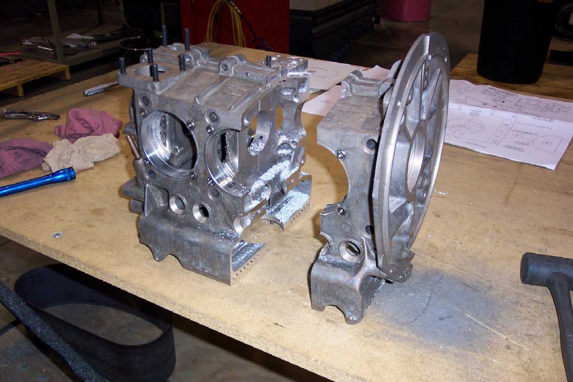
This is what your new case will look like.
The case comes with studs installed to hold the case together but I removed
them to do the machine work. |
|
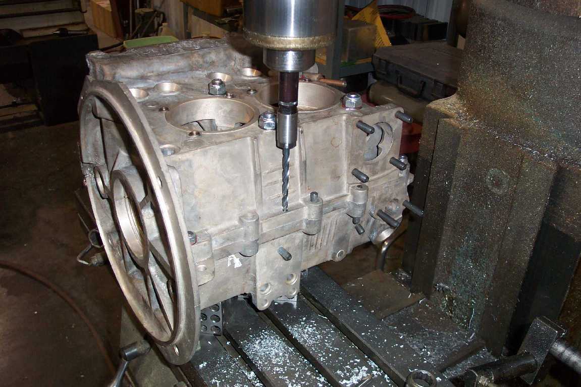
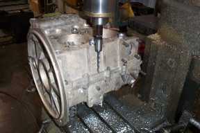
The first thing I did is drill and ream for
a 1/4" dowel. When the case is cut in half, one of the installed dowels
goes away with the scrap. The location doesn't really matter as long as you try
to put it as far from the other dowel as possible. You can see where I drilled
if you enlarge the picture. |
 |
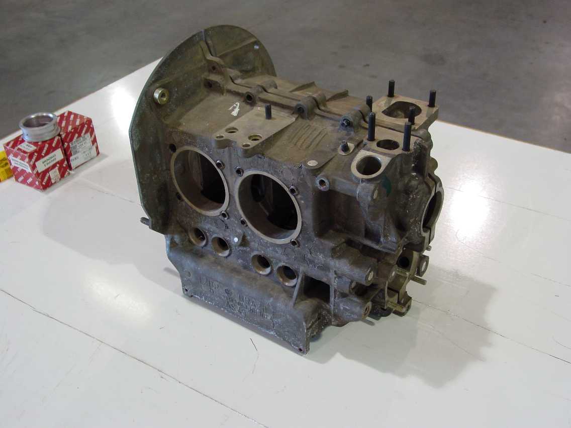
I purchased a complete VW aircraft engine on
ebay that I am using parts from for this engine. The engine I purchased came
from Team 38. It was brand new but when I tore it down I found some pitiful
machine work on the case. I wouldn't put that case in a car let alone an
airplane. The rest of the parts were very high quality. It came with a Scat
78mm crank and Scat individual heads which is why I wanted it in the first
place. The crank came from Great Plains because it has their Force One hub with
a 1/2-20 bolt. The hub is probably overkill for this engine but since I already
had it with a crank machined for it I figured what the heck. This is the setup
I used to bore the front bearing bore. |
 |
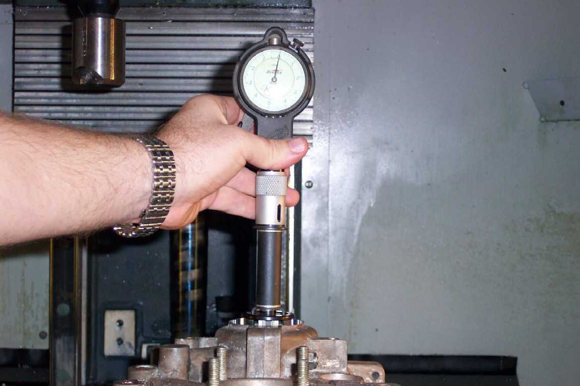
Great Plains instructions on their web site
for installing the Force One hub say to bore the front bearing bore .001"
smaller than the hub bearing measures. Here the bore is finished and I am
checking it with a Sunnen dial bore gage. If you enlarge the picture you will
see the needle exactly on zero. I cheated with the reading. It ended up
.0001" under nominal. I had to make you think I'm perfect. By the way, if
you are in the market for dial bore gages, buy Sunnen gages. They are the
best. |
 |
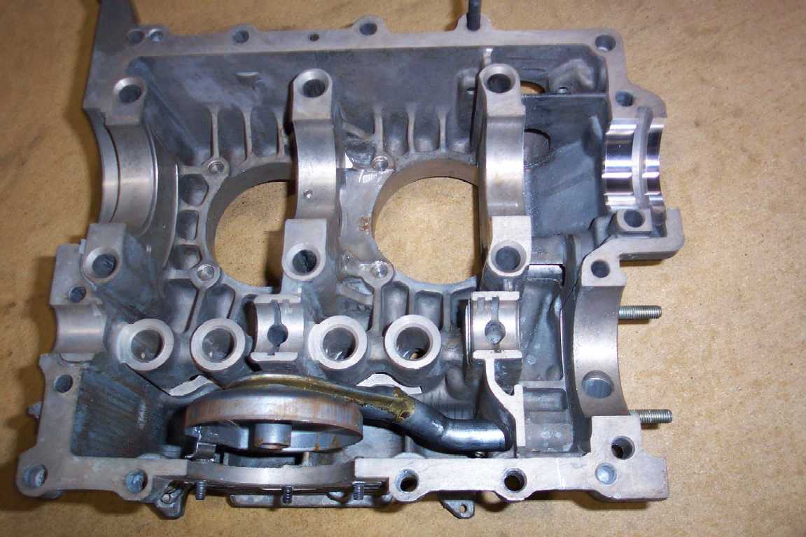
This is one case half after machining the
bearing bore for the hub bearing. The cast magnesium machines real
pretty. |
 |
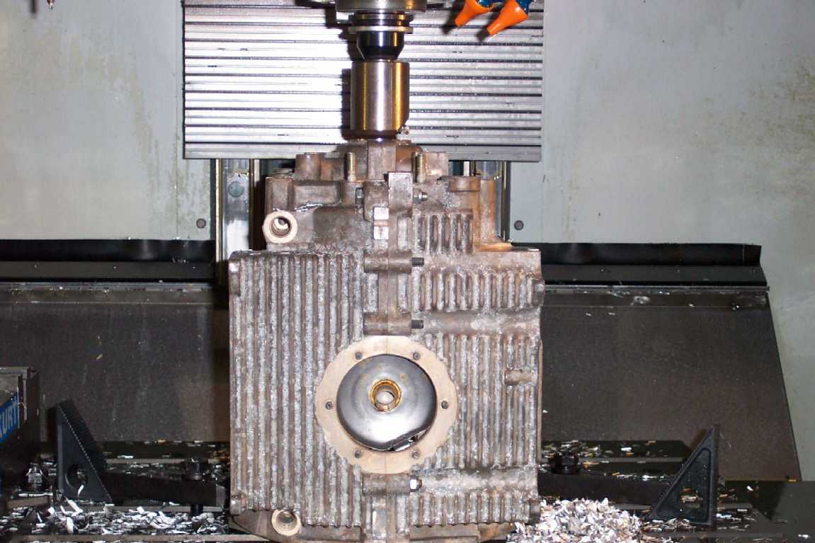
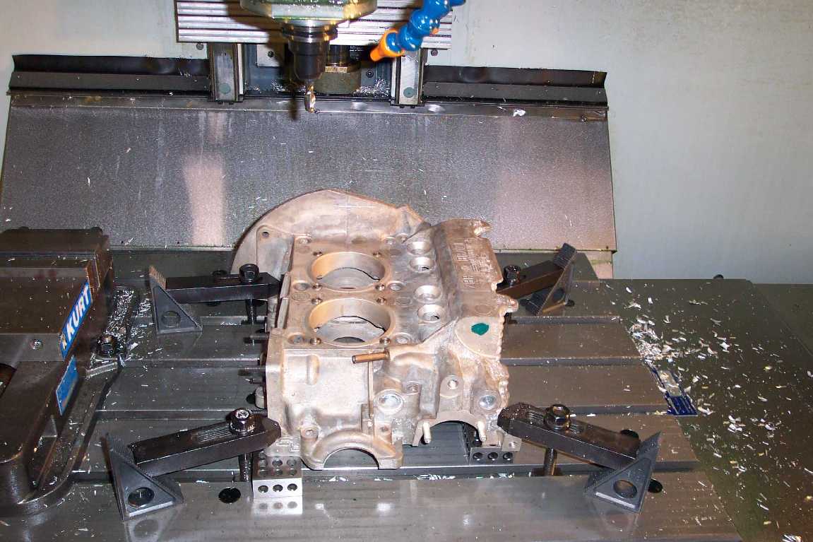
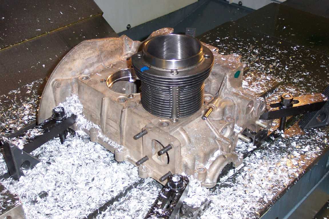
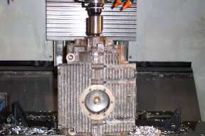
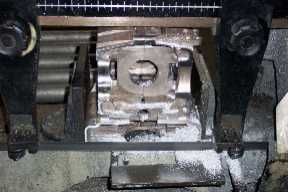
The next step was machining for the 94mm
cylinders. This is the setup I used. It was just clamped to 4 1-2-3
blocks. |
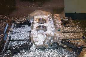 |
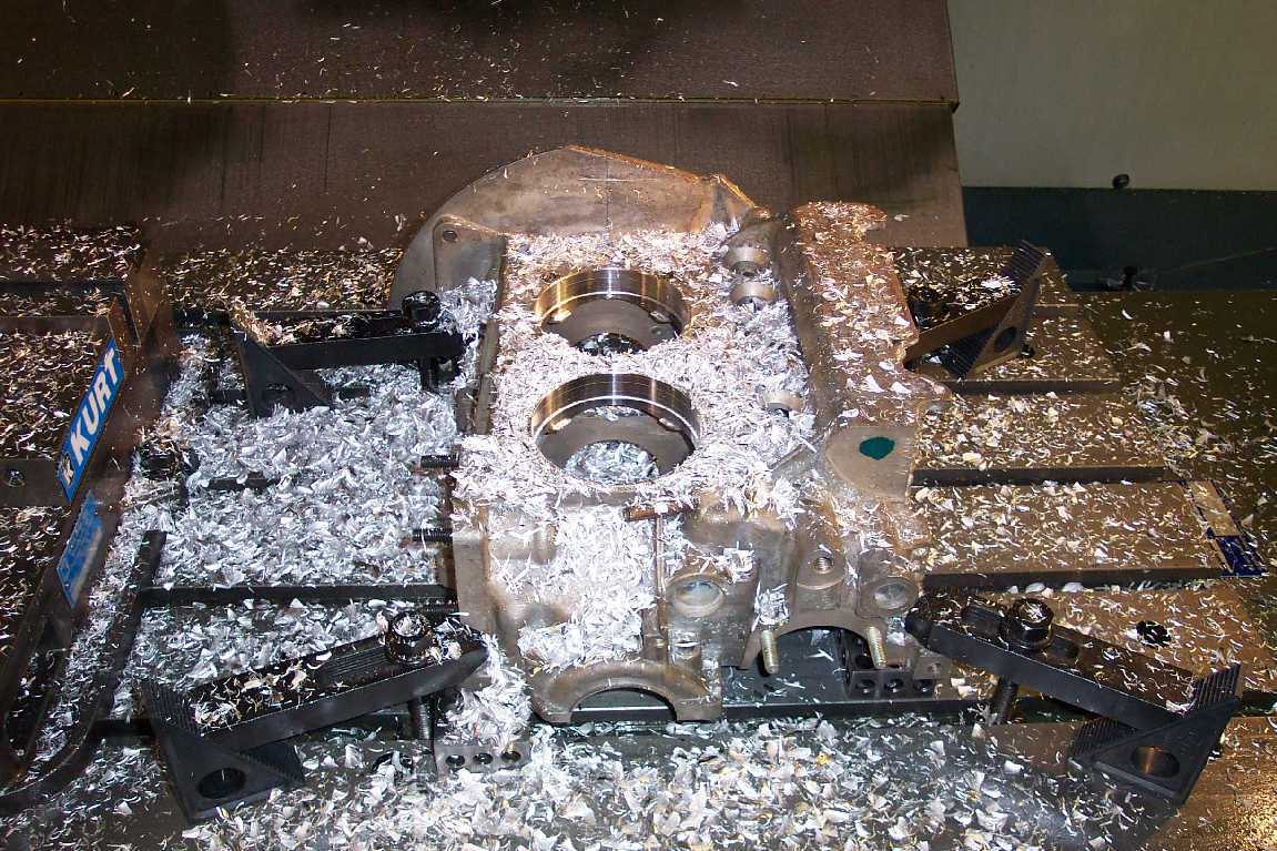
I circle interpolated the bores on the CNC
with an end mill to finish the bores. They didn't need to be as accurate as the
hub bearing bore so I didn't use a boring bar. I machined both cylinders on
this case half because I wanted to practice on the rear cylinder bore first in
case I programmed it incorrectly. I wish I hadn't now because I have to block
this rear cylinder bore off after I cut the case and It would have been easier
with the stock bore. Live and learn. |
 |
After machining, I checked for proper
cylinder fit before removing from the machine. |
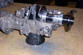 |
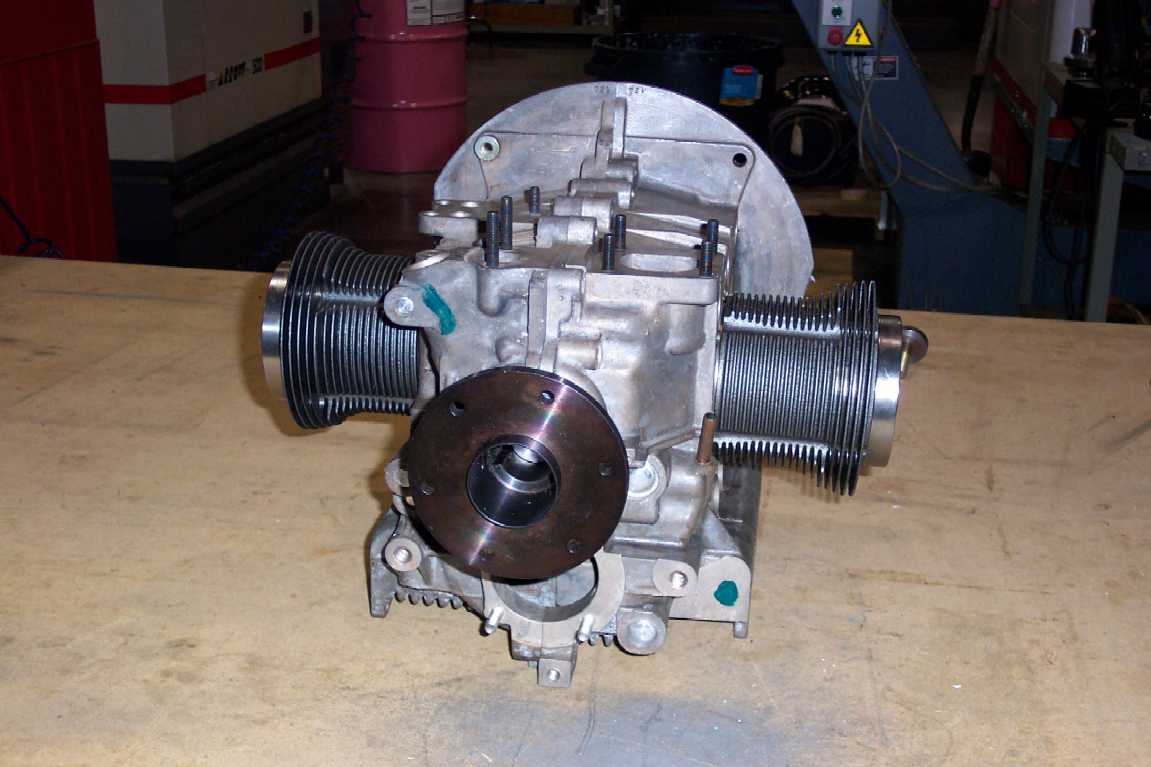
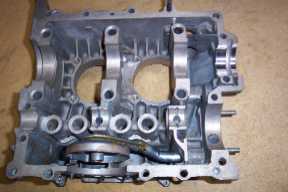
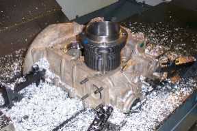
Once the cylinders fit the case I could
check for clearance of the rotating assembly. Here the crank is in the case
with the main bearings installed and one rod, piston and cylinder. According to
Great Plains, you should check each cylinder for clearance individually. Check
it with both case halves and a piston without rings. Rotate the crank to make
sure nothing hits the case. I am using Scat I-beam rods which are already
clearanced for a stroker crank. With a 78mm crank, the Scat rods don't hit the
case anywhere in my engine. I will be doing more checking later, but for now I
am happy I don't have to do any clearance work to the case. If I was using
stock rods or an 82mm crank, it wouldn't clear. |
 |
When I was checking clearance I had to stick
in another cylinder to see what it looked like. Pretty cool! |
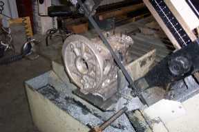 |
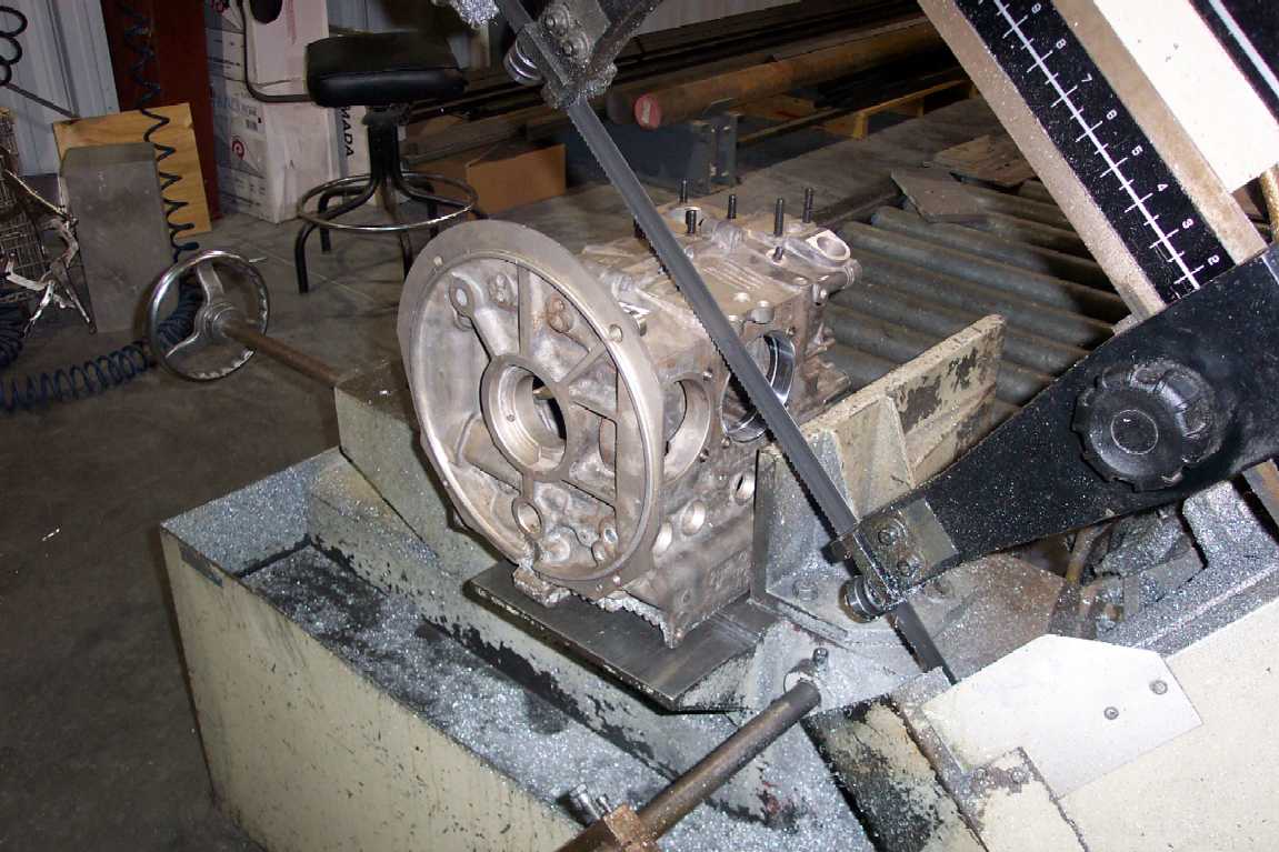
It's always fun putting expensive parts in a
saw and cutting them in half isn't it? Check your measurements 5 or 6 times to
make sure you aren't going to screw up. I cut mine long so I had plenty of room
to face it to length on the mill. None of the plans I purchased gives a good
measurement for where the crank ends and the case ends for proper location of
the mag. You get to figure this out yourself. I'll be waiting till later to do
some measuring before I finish the back of the case. I'll have to allow for the
plate on the back, make sure my engine mounts will work, and allow for a mag
drive on the crank and mag mount on the back plate. I'll let you know what I
do. |
 |
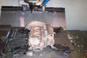
This is the case in the saw after the rough
saw cut. I sawed it very long. I will have to machine a lot of material
off. |
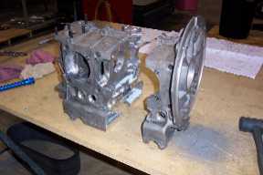 |
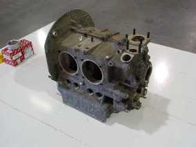
Here is the case out of the saw after being
cut. The pieces removed weigh 7 pounds. The information I found before I
decided to go this way lead you to believe that only 5 pounds are removed by
cutting the case and you add it all back with a back plate and engine mount.
I'm thinking some of these people just want to sell their plans. We'll see when
I'm done. There are advantages to both methods of conversion but I think I'll
save weight by using a mag instead of a stock ignition with a battery. I am
planning to make a back plate out of 3/4" aluminum. I will be removing
most of the material by machining pockets in the plate where the strength is
not needed leaving thin webs for strength. Doing this I can have engine mount
locations in the same place as the Mosler engine and I can build a motor mount
per the plans. Right now I am just talking and I haven't designed the thing yet
so I don't know if it will work. I'll keep you posted. |
|
|
|
|
|
|
|
|
|
|
|
|
 Engine Case